


EMC Testing Standards for Consumer Electronics
Electromagnetic Compatibility (EMC) is a key indicator to ensure electronic devices operate properly within an electromagnetic environment without causing interference to other equipment. The goal of EMC remediation is to guarantee that devices pass emc tests (such as radiated emissions, conducted emissions, immunity, etc.) and maintain stable long-term operation by optimizing design, shielding, filtering, and other methods. Below is the complete EMC inspection, testing, and remediation process.
1. emc testing and Problem Diagnosis
1.1 EMC Test Items
EMI (Electromagnetic Interference):Conducted Emissions (CE), Radiated Emissions (RE)
Applicable standards: CISPR 32, fcc part 15, GB 9254
EMS (Electromagnetic Susceptibility):ESD, EFT, Surge, RF Immunity (RS/CS)
Applicable standards: iec 61000-4 Series, EN 55035
Special Industry Requirements:Automotive (CISPR 25), Military (MIL-STD-461)
Applicable standards: Industry-specific standards
1.2 Problem Diagnosis Methods
Spectrum Analysis (for EMI issues):
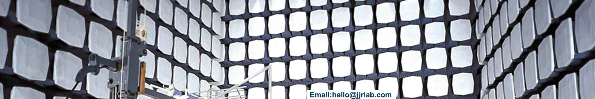
Use a spectrum analyzer to locate frequency points that exceed limits (e.g., radiated emission above 30 MHz).
Use near-field probes to scan PCB, cables, and interfaces to find noise sources such as switching power supplies or clock signals.
Immunity Failure Analysis (for EMS issues):
Check if the ESD discharge path is intact (e.g., poor chassis grounding).
During EFT/Burst immunity tests, observe if the device resets or experiences communication failures.
2. Core Strategies for EMC Remediation
2.1 Source Suppression (Most Effective)
Reduce High-Frequency Noise:
Optimize switching power supply layout to reduce ringing, for example by adding buffering circuits.
Apply spread spectrum technology to clock signals to lower peak emissions.
Optimize PCB Design:
Route critical signals (such as USB, HDMI) on inner layers to minimize surface radiation.
Ensure continuous ground planes to avoid common-mode noise caused by ground splits.
2.2 Blocking the Propagation Path
Shielding:
For metal chassis, use conductive foam or copper tape at seams.
For plastic chassis, apply conductive paint or add metal shielding covers.
Filtering:
Power input lines: Use common mode chokes and X/Y capacitors, while observing leakage current limits.
Signal lines: Use ferrite beads and π-type filters, effective for noise above 100 MHz.
2.3 Protection of Sensitive Circuits
ESD Protection:
Add TVS diodes on interface signal lines (e.g., SRV05-4 for USB).
Ensure low impedance grounding of metal enclosures (ground resistance less than 1 ohm).
Surge Protection:
For power lines, combine MOV, TVS, and Gas Discharge Tubes (GDT).
For communication lines, use opto-isolation or common mode chokes.
3. Typical Remediation Cases
Case 1: Smart Home Device Radiated Emission Exceeds Limit
a. Issue:Wi-Fi module 2.4 GHz harmonics caused radiated emission test failure.
b. Remediation:Add a three-terminal filter at the Wi-Fi module power input; lay ground planes around the PCB antenna and keep it away from metal structures.
c. Result:Radiation reduced by 10 dB, passed fcc certification.
Case 2: Industrial PLC Fails EFT Test
a. Issue:±2kV EFT caused PLC communication interruptions.
b. Remediation:Add a 100 μH common mode choke at power entry; add TVS diode and ferrite bead filters on RS-485 interface.
c. Result:Passed ±4kV test with stable communication.
4. EMC Remediation Verification
a. Retest EMC items to ensure all exceedances are resolved.
b. Conduct environmental adaptability tests (check EMC stability under temperature extremes and vibration).
c. Perform long-term aging tests (continuous 72-hour operation with EMC parameter monitoring).
5. Summary
The core principles of EMC remediation include:
a. Locating problems using spectrum analysis and near-field scanning.
b. Applying layered treatment: source suppression first, then shielding and filtering, and finally protective design.
c. Performing regression testing to ensure remediation effectiveness without impacting device functionality.
Email:hello@jjrlab.com
Write your message here and send it to us
 Amazon Toys TIC DV Validation
 Austrian Amazon EPR Mandatory Compliance
 The Differences Between CTA Network Access Certifi
 Where to Get German LFGB Testing Done?
 966 Fully Anechoic Chamber
 Power Adapter UL1310 Certification
 Standard for Air Conditioners and Dehumidifiers: I
Guide to Children's Product Safety and Compliance
Standard for Air Conditioners and Dehumidifiers: I
Guide to Children's Product Safety and Compliance
Leave us a message
24-hour online customer service at any time to respond, so that you worry!