


Best Radiated Emissions Testing Lab
Radiated Emission testing measures the radiated disturbance field strength propagated by the EUT (Equipment Under Test) through space. It can be divided into magnetic field radiation and electric field radiation. The former is primarily aimed at luminaires and induction cookers, while the latter is widely applicable to most products. In addition, there are power radiation requirements (referred to as disturbance power) for home appliances, power tools, and the auxiliary equipment of AV (Audio/Video) products.
radiated emission testing Standards
a) Electric Field Radiation: CISPR 22, CISPR 13, CISPR 11, CISPR 14-1, CISPR 15 (specific categories of toys).
b) Magnetic Field Radiation: CISPR 15 (luminaires with an operating current frequency exceeding 100Hz), CISPR 11 (induction cookers).
c) Disturbance Power: CISPR 14-1 (except for certain equipment with an operating frequency not exceeding 9kHz), CISPR 13 (only for auxiliary equipment).
Radiated Emission Testing Methods
1) Radiated Emission Testing Instruments and Equipment
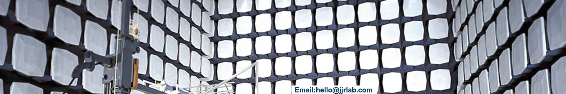
a) Electric Field Radiation: Receiver (below 1GHz), spectrum analyzer (above 1GHz), anechoic chamber, and antennas (below 1GHz generally uses a combination of biconical and log-periodic antennas or a broadband composite antenna; above 1GHz uses a horn antenna).
b) Magnetic Field Radiation: Receiver, triple-loop antenna, or a single small loop remote antenna.
c) Disturbance Power: Receiver, power absorbing clamp.
Note: The receiver must comply with CISPR 16-1-1 requirements, the antennas and site must comply with CISPR 16-1-4 requirements, and the absorbing clamp must comply with CISPR 16-1-3 requirements.
2) Radiated Emission Test Setup
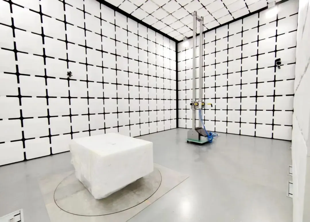
a) Electric Field Radiation: Setup is divided into table-top and floor-standing configurations, identical to conducted emissions. Because radiated emission results are particularly sensitive to product arrangement, the test samples (including the product, auxiliary equipment, and all cables) must be arranged strictly according to the standards.
b) Magnetic Field Radiation: Triple-loop antennas of different sizes have limitations on the maximum EUT dimensions they can test. Taking a 2m diameter triple-loop antenna as an example, an EUT less than 1.6m in length can be tested in the center of the antenna. According to CISPR 11, induction cookers exceeding 1.6m are measured using a 0.6m diameter single loop remote antenna at a 3m distance, with a minimum height of 1m.
c) Disturbance Power: Divided into table-top and floor-standing configurations. Table-top equipment is placed on a 0.8m high non-metallic table, at least 0.8m away from other metallic objects (typically the metallic inner wall of a shielded room; this distance requirement is at least 0.4m in CISPR 14-1). Floor-standing equipment is placed on a 0.1m non-metallic support. The cable under test (LUT) is laid out on a power absorbing clamp guide rail that is 0.8m high and 6m long. The absorbing clamp is placed over the cable, with the current transformer end facing the EUT. If the EUT has other cables, disconnect them if it doesn't affect functionality; if they cannot be disconnected, isolate them using ferrite absorbing clamps.
3) Radiated Emission Testing Frequency Bands
Electric field radiation is generally 30MHz - 1GHz (some products require testing above 1GHz, depending on specific standard provisions). Magnetic field is 9kHz - 30MHz. Disturbance power is 30MHz - 300MHz.
4) Radiated Emission Testing Limits
Limits vary depending on the standard, the test site distance (3m, 10m, or other dimensions), and the specific product classification (Group 1/2, Class A/B).
5) Radiated Emission Testing Process
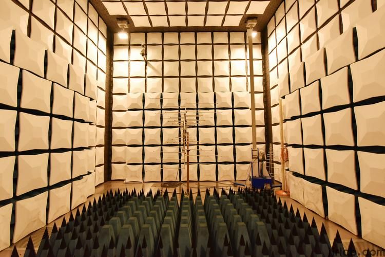
a) 30MHz - 1GHz Electric Field Radiation: Conducted in a semi-anechoic chamber. The EUT rotates 360 degrees on a turntable, and the antenna ascends and descends between 1m and 4m in height to find the maximum radiation value. Results are expressed in QP (Quasi-Peak) values. Both vertical and horizontal antenna polarizations are tested.
b) Electric Field Radiation Greater Than 1GHz: ITE (Information Technology Equipment) with an operating frequency exceeding 108MHz and ISM (Industrial, Scientific, and Medical) equipment exceeding 400MHz require this testing. It is measured at a 3m site using a spectrum analyzer. The testing method for ITE equipment is fundamentally the same as the 30MHz-1GHz range, and results are expressed in Peak and AV (Average) values. ISM products are slightly different; they must be tested in a fully anechoic chamber. The antenna is kept at the same height as the product and does not ascend or descend, while the turntable continues to rotate to find the maximum radiation value.
c) Substitution Method: Uses ERP (Effective Radiated Power) as a substitute, which is then converted into a field strength value. This is frequently used in RF testing but rarely in conventional EMC. The purpose of the substitution method is to test the enclosure radiation of the EUT. All detachable cables must be removed, and non-detachable cables must be fitted with ferrite magnetic rings. First, Antenna A and a receiver measure the EUT's maximum disturbance value. Then, Antenna B replaces the EUT, and the signal generator's output power is adjusted until the measuring receiver reaches the same value. The input power to the substitution Antenna B is recorded as the EUT's enclosure radiated power. Antenna selection depends on the test frequency.
d) Magnetic Field Radiation: Magnetic field radiation testing using a triple-loop antenna is straightforward; the sample is placed at the center of the antenna, and one set of magnetic field radiation results is measured for each of the three axes (X/Y/Z). When using a single small loop antenna, the antenna is placed perpendicular to the ground, with its lowest point 1m above the ground. Because it is a near-field measurement that also accounts for ground reflection, the measured values reflect the horizontal and vertical magnetic field components of the EUT.
e) Disturbance Power: This must be performed on all equipment cables (including auxiliary equipment cables) that exceed 25cm in length. Because disturbances at various frequency points within the 30-300MHz range distribute as standing waves along the tested cable, it is necessary to pull the power absorbing clamp along the guide rail during measurement to locate the position of maximum disturbance power for each final test frequency point (roughly at a distance of half a wavelength from the equipment).
Radiated Emission Test Results Judgment
The results are evaluated by comparing them against the standard limit line. Values below the line result in a PASS, while values exceeding the line result in a FAIL.
Radiated Emission Testing Precautions
The test setup remains the most critical aspect of the testing process. Furthermore, because this is high-frequency testing, environmental factors such as the test site and equipment quality are crucial elements that will significantly impact the final results.
Radiated Emission Testing Range
30MHz - 18.5GHz
Email:hello@jjrlab.com
Write your message here and send it to us
 How to Apply for the IEC/UL 62368 Test Report
 Which Laboratory Can Process Lithium Battery EN 50
 Bicycles on Amazon: 16 CFR 1512 and GCC Certificat
 What is the Cycle for UL 2271 Certification for Li
 The Two Certification Schemes of Hong Kong OFTA
 What is the difference between ANSI C18.3M and UL4
 Amazon Button and Coin Cell Battery ANSI C18.3M Ce
 Button Cell Battery ANSI C18.3M Testing
Leave us a message
24-hour online customer service at any time to respond, so that you worry!