


Radiated Emission Testing Services
Overview of Radiated Emission (RE) Testing
Radiated Emission (RE) testing measures the electromagnetic disturbances emitted by the Equipment Under Test (EUT) through space. These emissions can be categorized into:
- Magnetic Field Radiation: Typically for lamps and induction cookers.
- Electric Field Radiation: More commonly applied across various products.
In addition, appliances, power tools, and AV auxiliary equipment must meet requirements for conducted power emissions (also referred to as disturbance power).
")
Radiated Emission (RE) Testing Standards
Applicable standards include:
- CISPR22 / EN55022: Information technology equipment
- CISPR13 / EN55013: Audio/video products
- CISPR11 / EN55011: Industrial, scientific, and medical (ISM) equipment
- CISPR14-1: Household appliances
- CISPR15 / EN55015: Lighting equipment
- YY0505, GB/T 18268, GB 4824
- CISPR15: For lighting with operating frequency above 100Hz
- CISPR11: For induction cookers
- CISPR14-1: Except for equipment operating below 9kHz
- CISPR13: Only for auxiliary equipment
Radiated Emission (RE) Testing Methods
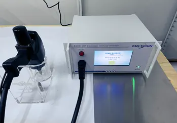
1) Testing Instruments and Equipment
- Electric Field Radiation:
- Below 1GHz: Receiver, anechoic chamber, biconical/log-periodic or broadband composite antennas
- Above 1GHz: Spectrum analyzer, horn antenna
- Magnetic Field Radiation:
- Receiver, tri-axial loop antenna or single-loop remote antenna
- Disturbance Power:
- Receiver, power absorption clamp
All instruments must conform to:
- CISPR16-1-1for receivers
- CISPR16-1-4for antennas and test sites
- CISPR16-1-3for absorption clamps
2) Test Setup
- Electric Field Radiation:
- Setup varies for tabletop vs. floor-standing units
- Arrangement of EUT, auxiliary equipment, and cables must strictly follow the standard
- Magnetic Field Radiation:
- Limited by the size of the tri-axial antenna
- EUT must fit within a 2m diameter if centered
- For EUT > 1.6m (e.g., large induction cookers), use a single-loop antenna 3m away at a minimum height of 1m
- Disturbance Power:
- Tabletop devices: On a 0.8m high non-metal table, ≥0.8m from metal (≥0.4m as per CISPR14-1)
- Floor-standing devices: On 0.1m non-metal support
- Cables (LUT): Placed on a 6m long, 0.8m high rail with power clamp; isolate non-detachable cables with ferrites
3) Test Frequency Ranges
- Electric Field Radiation: 30MHz–1GHz (some standards require above 1GHz)
- Magnetic Field Radiation: 9kHz–30MHz
- Disturbance Power: 30–300MHz
4) Limit Values
Limits vary depending on:
- Distance (3m, 10m, etc.)
- Product classification: Group 1/2, Class A/B
5) Testing Procedures
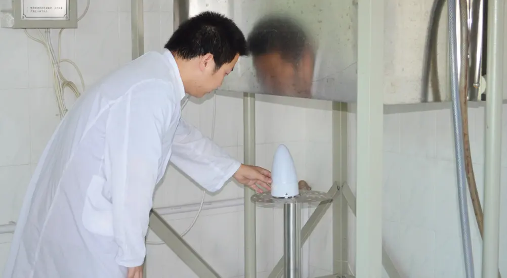
- 30MHz–1GHz Electric Field Radiation:
- Performed in a semi-anechoic chamber
- EUT rotates 360° on a turntable; antenna scans vertically from 1–4m
- Measure both vertical and horizontal polarization; report Quasi-Peak (QP) values
- >1GHz Electric Field Radiation:
- Required for ITE (>108MHz) and ISM (>400MHz)
- Measured at 3m using a spectrum analyzer
- ITE: Same setup as sub-1GHz, with Peak and Average values
- ISM: Full anechoic chamber, antenna at same height as EUT, fixed height, rotating turntable
- Substitution Method:
- Used to determine effective radiated power (ERP)
- All removable cables must be disconnected or shielded with ferrite
- Replace EUT with antenna B, adjust signal generator until same disturbance level is measured as with EUT
- Magnetic Field Radiation:
- Tri-loop: Measure in X, Y, Z directions
- Single-loop: Vertically placed at 1m above ground, accounting for near-field and reflection
- Disturbance Power:
- Applied to cables >25cm
- Power clamp moved along rail to locate peak emission per frequency
Determining Test Results
Compare the measurement from the detector to the limit line:
- Below limit: PASS
- Above limit: FAIL
Important Considerations
- Test setup is critical
- High-frequency testing demands strict attention to test site quality and equipment configuration
Testing Range
30MHz to 18.5GHz
Email:hello@jjrlab.com
Write your message here and send it to us
 Amazon Toys TIC DV Validation
 Austrian Amazon EPR Mandatory Compliance
 The Differences Between CTA Network Access Certifi
 Where to Get German LFGB Testing Done?
 966 Fully Anechoic Chamber
 Power Adapter UL1310 Certification
Standard for Air Conditioners and Dehumidifiers: I
Guide to Children's Product Safety and Compliance
Power Adapter UL1310 Certification
Standard for Air Conditioners and Dehumidifiers: I
Guide to Children's Product Safety and Compliance
Leave us a message
24-hour online customer service at any time to respond, so that you worry!