


Conducted Emission Testing Services
Overview of Conducted Emissions
Conducted emissions, often referred to as disturbance voltage testing, apply to any product with power lines, including many DC-powered devices. In addition, conducted emission requirements also apply to signal/control lines in many standards. The limits are usually expressed in terms of disturbance voltage or disturbance current (which can be converted between each other). Insertion loss testing in lighting equipment (expressed directly in dB) also falls under the category of conducted testing.
")
Conducted Emission Testing Standards:
- CISPR22 (ITE), EN55022, GB9254
- CISPR14-1 (Household appliances and tools), EN55014-1, GB4343
- CISPR13 (AV), EN55013, GB13837
- CISPR15 (Lighting), EN55015, GB17743
- CISPR11 (ISM), EN55011
- EN61326
- EN60601-1-2
- EN301489
- YY0505
- GB/T 18268
- GB 4824
Conducted Emission Testing Methods:
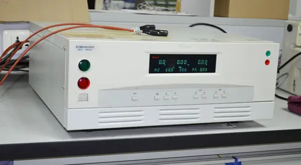
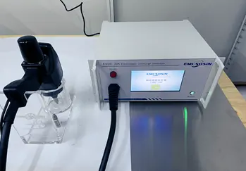
1) Instruments and Equipment:
Includes receiver, LISN (Line Impedance Stabilization Network or AMN - Artificial Mains Network), artificial hand, passive voltage probes, current probes (along with CDN for current probes, capacitive voltage probe), DIA (Discontinuous Interference Analyzer for CISPR14-1), complete set for insertion loss measurement, and a PC. DIA must comply with CISPR16-1-1; other auxiliary equipment must meet CISPR16-1-2 requirements.
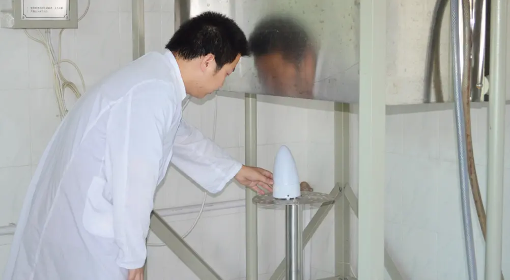
2) Test Setup:
Desktop and floor-standing setups differ. For desktop equipment: 80 cm from LISN, 40 cm from the grounding plane (can be a horizontal ground plate or vertical inner wall of a shielded room). Floor-standing devices: distance from ground plate varies by standard. CISPR14-1/15: 10 cm ± 25%, CISPR13: up to 12 mm, CISPR22: up to 15 cm, CISPR11: no fixed distance, just insulated from the ground plate. Auxiliary equipment placement varies by standard: in CISPR22, auxiliary devices should be 10 cm from the EUT, and all interconnecting cables must be at least 40 cm from the ground plane. Handheld Class II devices require a simulated hand. Self-ballasted fluorescent lamps in CISPR15 should be covered with a metal auxiliary cone.
3) Frequency Range:
Typically 150 kHz – 30 MHz. Exception: CISPR15 (disturbance voltage 9 kHz – 30 MHz, insertion loss 150 kHz – 1.605 MHz).
4) Limits:
Vary based on standard and product classification (e.g., Group 1/2, Class A/B).
5) Testing Procedures:
a) AC/DC Power Port Disturbance Voltage:
Most common test. Connect power plug to LISN, receiver RF input to LISN RF output (with optional RF attenuator or pulse limiter). Switch L/N on LISN to test common-mode disturbance voltage.
b) Discontinuous Interference:
Required by CISPR14-1 and derived standards. Use DIA with LISN or combine an oscilloscope with the receiver. The oscilloscope observes disturbance duration, and the receiver measures amplitude.
c) Load Port Disturbance Voltage:
Required in CISPR14-1, 15, and 11. Use a passive voltage probe by stripping insulation from load lines and measuring disturbance voltage from terminals to ground. If the rated current is too high for any LISN, a voltage probe can be used for power port disturbance voltage measurement.
d) Communication Line Disturbance Voltage/Current:
Addressed in CISPR22. Different cable types have different test methods, detailed in Annex C with pros and cons in Annex F. Measurement uses combinations of current probes, CDNs, 150Ω termination resistors, and capacitive voltage probes. The line’s impedance to ground must be 150Ω. Results can be in dBuA (current) or converted to dBuV (voltage), with a 44 dB conversion difference (150Ω impedance).
e) Insertion Loss:
Mentioned in CISPR15. Uses RF sine wave generator, balun transformer, simulated lamp, LISN, and a receiver to compare voltages and calculate insertion loss.
Result Determination:
Measurement results from the receiver detector (QP/AV) are compared with the limit line. Below the limit = PASS, above = FAIL.
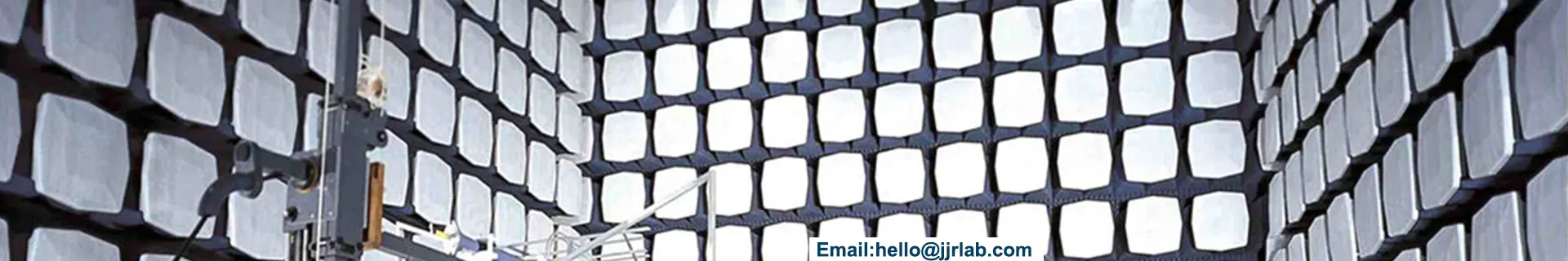
Key Considerations:
As conducted emission testing measures common-mode noise to ground, setup is critical. Once setup is correct, measurement with the receiver is straightforward. Differences in setup can lead to variations in results. Unresolved issue: use of pulse limiters at the receiver RF input. Some labs use them to protect receivers;
Email:hello@jjrlab.com
Write your message here and send it to us
 What Products Require Direct Verification by Amazo
 Amazon Toys TIC DV Validation
 Austrian Amazon EPR Mandatory Compliance
 The Differences Between CTA Network Access Certifi
 Where to Get German LFGB Testing Done?
 966 Fully Anechoic Chamber
Power Adapter UL1310 Certification
Standard for Air Conditioners and Dehumidifiers: I
966 Fully Anechoic Chamber
Power Adapter UL1310 Certification
Standard for Air Conditioners and Dehumidifiers: I
Leave us a message
24-hour online customer service at any time to respond, so that you worry!