


Do Sensors Need to Pass FCC Part 15.231 Certification?
fcc part 15.231 is a radio frequency radiation specification formulated by the Federal Communications Commission (fcc) of the United States for intermittent radiating devices. It aims to prevent interference with other radio services (such as aviation communications and public safety frequency bands) by limiting the emission interval, duration and duty cycle of equipment. It applies to products operating periodically in the frequency bands of 40.66-40.70 MHz and above 70 MHz (e.g., 315 MHz and 433.92 MHz).
Applicable Products and Classification
15.231(a)
15.231(a) Category Products: Limited to transmitting control signals (data transmission is acceptable as an auxiliary function)
Its core feature is short-duration, discontinuous transmission of control commands. Emission must stop quickly after the control switch is released. Typical products include:
• Household appliance remote controls (IR/RF remote controls for TVs, air conditioners, projectors)
• Garage door / access control remote controls
• Trigger transmitters for alarm systems (e.g., wireless signal transmitters for smoke alarms)
• Wireless controllers for industrial equipment (e.g., remote operating handles for cranes)
• Drone remote controls (basic models only for control command transmission, excluding image transmission)
Note: Continuous transmission (non-trigger sustained emission), voice, video and radio-controlled toys are not covered by this section.
15.231(e)
Periodic Products (periodic emission, continuous/audio & video transmission permitted)
Its core feature is fixed-cycle emission with short single transmission time and long interval time. Typical products include:
• Wireless temperature detectors (regularly sending temperature data to gateways, e.g., temperature sensors for cold chain containers)
• Smart electric / water meters (periodically uploading metering data)
• Environmental monitoring sensors (e.g., temperature & humidity sensors, PM2.5 sensors for regular data feedback)
• Pet tracking collars (periodically sending location information without real-time continuous transmission)
• Asset trackers (e.g., positioning tags for logistics containers with regular location reporting)
Note: Applicable to all operation types, including continuous transmission, voice, video and radio-controlled toys prohibited under 15.231(a).
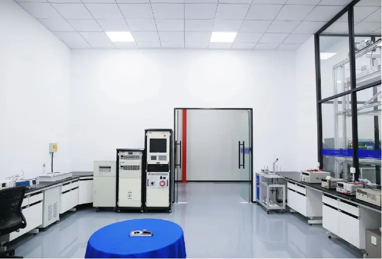
Test Items
")
Note: AC conducted emission test items are not applicable to battery-powered products.
Antenna Requirement
1. Equipped with permanently connected antennas
2. Equipped with uniquely coupled antennas on intentional radiators
3. Equipped with reverse polarity SAM connectors
• Antennas must be permanently connected (e.g., PCB printed antennas) and non-replaceable by users.
• For installation on intentional radiators, specially coupled antennas with reverse polarity SAM connectors shall be configured to ensure equipment antenna matching and avoid signal abnormalities.
In short: Antennas shall be non-detachable and non-replaceable, and fixedly matched with equipment to prevent excessive RF indicators caused by user antenna replacement.
AC Power Conduction Emission
• Limit Values
")
• Test Data
")
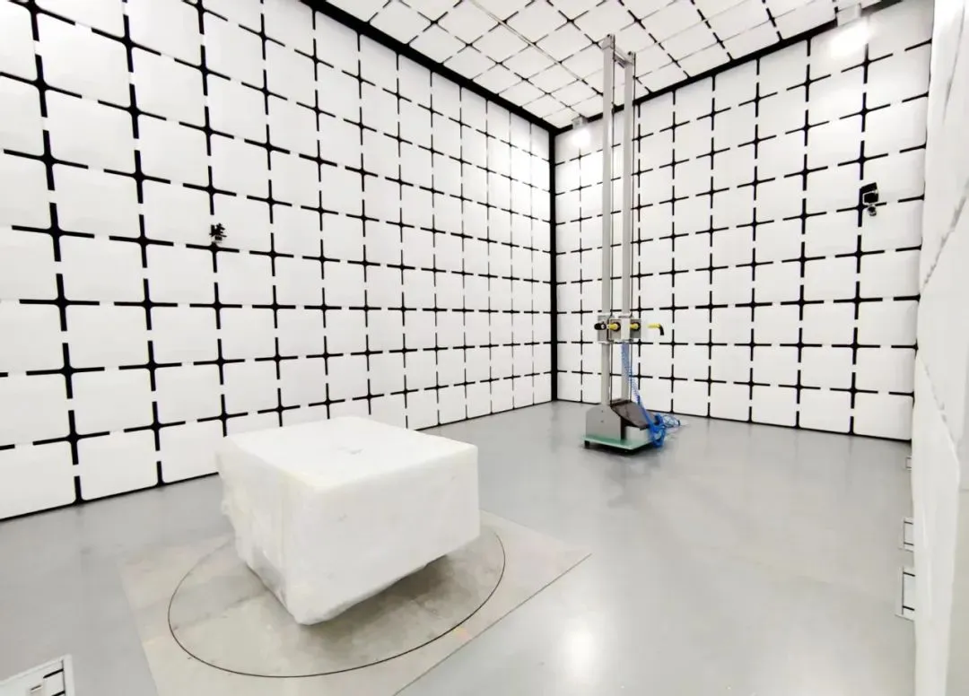
Radiated Emission
• Test Frequency Range
")
• Limit Requirements
Unless otherwise specified in Paragraph (g), intentional radiators regulated by this section shall not have fundamental emission frequencies within 54-72 MHz, 76-88 MHz, 174-216 MHz or 470-806 MHz. However, equipment complying with other specific subsections of this part (e.g., §15.231 and §15.241) is allowed to operate in the above frequency bands.
Field Strength of Fundamental and Harmonic Emissions
• FCC PART 15(a) Limit Values
• FCC PART 15(e) Limit Values
AV Value Calculation Methods
Method 1: Read data points via receiver AV detection
Method 2: PK values are obtained through measurement, while AV values are calculated based on duty cycle.
Formula:
AV=PK+AVfactor
AVfactor=20log(DutyCycle)
DutyCycle=Ton/Tall×100
• Tall: A complete emission cycle (including Ton and Toff)
• Ton: Emission duration within one cycle
Test Data Interpretation
• Low-frequency spurious emission
• High-frequency spurious emission & field strength
20dB Bandwidth
Limit Requirements
For devices operating above 70 MHz and below 900 MHz, the emission bandwidth shall not exceed 0.25% of the center frequency. For devices operating above 900 MHz, the emission bandwidth shall not exceed 0.5% of the center frequency. Bandwidth is defined at the point 20 dB below the modulated carrier.
Calculation rules:
• ![]() : Maximum bandwidth =
: Maximum bandwidth = ![]()
• ![]() : Maximum bandwidth =
: Maximum bandwidth = ![]()
Example with 433.92 MHz:
Bandwidth upper limit = ![]()
Spectrum Analyzer Parameter Settings
• Span: 2 to 5 times of OBW
• RBW: 1% to 5% of OBW
• VBW: 3 times of RBW
Transmit Time
15.231(a)
1. Manually triggered devices (manually operated transmitters with switches): Emission shall stop within 5 seconds after the switch is released.
2. Automatically activated devices: Emission shall stop within 5 seconds after activation.
Note: The sweep time shall not be less than 8 seconds.
Release Time Measurement
15.231(e)
1. Single transmission duration shall not exceed 1 second.
Silent Period
15.231(e)
1. The silent interval between transmissions shall be at least 30 times the transmission duration.
2. In any case, the silent period shall not be less than 10 seconds.
Duty Cycle
Calculation Formula
Dutycyclefactor=20log(Dutycycle)
or
Dutycycle=ontime/0.1secondsorperiod,whicheverisless
Calculation Example:
Tontime=1.15×16+0.42×9=22.18ms
Tperiod=51.50ms
Dutycycle=Tontime/Tperiod=22.18/51.50=43.07
Dutycyclefactor=20log10(0.4307)=−7.32
Case Analysis
433.92 MHz Alarm Sensor
Category: 15.231(a)
Test Results:
• Antenna Requirement: PASS
• AC Conduction Emission: N/A
• Radiated Emission: PASS
• 20dB Bandwidth: PASS
• Time Measurement: PASS
• Duty Cycle: PASS
Email:hello@jjrlab.com
Write your message here and send it to us
 How to get a UL Test Certificate
 How to get a DOE Certificate of Compliance
 California 65 Compliance Certificate
 Amazon Bluetooth Earphone Certification Guide
 Why Do Plush Toys Need CPC Certification?
 Cargo Transport Identification & Compliance MS
 Carpet CPC/GCC/CE Certification and Customs Cleara
 Infant Carrier CPC Certification and ASTM F2236 Re
Leave us a message
24-hour online customer service at any time to respond, so that you worry!