


How to Prepare for Wireless Product Certification Testing?
Anyone in the wireless product industry knows that products must pass certification testing before hitting the market. However, if you fail to prepare a basic fixed-frequency prototype before sending it to the lab, you will not only waste time but also risk incurring high re-testing costs!
This guide systematically explains the preparation work for conducted and radiated fixed-frequency prototypes, covering hardware processing and software control, and provides a step-by-step tutorial on correctly preparing prototypes for certification testing.
I. Two Types of Prototypes: Conducted vs. Radiated – What’s the Difference?
1. Conducted Fixed-Frequency Prototype
Core Requirements:
① Antenna must be cut off
② SMA coaxial cable must be soldered
③ Fixed-frequency software must be running
Purpose: Test the performance of the RF chip itself and eliminate antenna variables. This is the "basic skill" for verifying hardware design.
2. Radiated Fixed-Frequency Prototype
Core Requirements:
① Antenna must remain intact
② Fixed-frequency software must be running
Purpose: Simulate real-world usage scenarios and test the performance of the complete device via antenna radiation.
In short: Conducted testing evaluates the "chip", while radiated testing evaluates the "device". Both require fixed-frequency operation, and the key difference lies in whether the antenna is intact.
Four Fixed-Frequency Control Methods – There’s One for Everyone
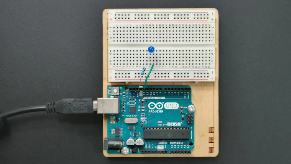
1. Direct Connection Method (Beginner-Friendly)
Operation: Directly connect the prototype to a computer using a USB cable
Applicable Scenarios:
① The prototype has a built-in USB debugging port
② Supports plug-and-play communication
③ No disassembly required; simple operation
Precautions:
① Ensure the computer can recognize the COM port
② Install the correct driver software
2. Serial Port Board Adapter Method (Universal Solution)
Operation: Lead out test wires → Connect to serial port board → Connect to computer
Four Wires to Be Led Out:
① TX (Transmit Data Line)
② RX (Receive Data Line)
③ GND (Ground Line)
④ VCC (Power Line)
Two Leading-Out Methods:
① Method A: Lead out from an external interface
② Method B: Lead out from internal test points (more commonly used)
3. Signaling Mode Method (Exclusive for Cellular Products)
Applicable Products: 4G/5G modules, cellular IoT devices
Working Principle:
The prototype enters signaling mode → Connect to the lab’s base station simulator → The base station fully controls the prototype’s transmission
Advantages: Standardized testing with high efficiency; a mandatory method for operator warehouse entry testing.
4. Customized Solution (Advanced Method)
Any method works as long as it achieves one goal: enabling the prototype to transmit stably at a fixed frequency!
Practical Operation Guide (with Detailed Steps)
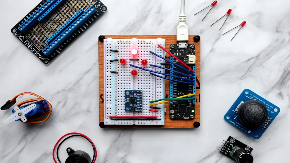
Step 1: Hardware Preparation
Conducted Prototype Operation Process:
1. Locate the antenna feed point
2. Carefully cut off the antenna with a hot air gun
3. Solder a high-quality SMA coaxial cable
4. Use a multimeter to check if the connection is secure
Tool List:
① Hot air gun/soldering iron
② SMA connector
③ Coaxial cable (RG178 recommended)
④ Multimeter
⑤ Magnifying glass
Step 2: Software Configuration
Firmware Burning Key Points:
A. Use dedicated fixed-frequency test firmware
B. Confirm the firmware supports the following functions:
① Lock to a specific channel
② Set fixed power
③ Continuous transmission mode
④ Debugging information output
Computer-Side Configuration:
Python |
Step 3: Connection Verification
Verification Checklist:
① The computer recognizes the COM port
② The fixed-frequency software can connect to the prototype
③ Frequency and power can be set
④ A stable signal is visible on the spectrum analyzer
Troubleshooting Guide: Common Problems and Solutions
Problem 1: Unstable Connection
Possible Causes:
① Poor solder joints
② Low-quality cables
③ Incompatible drivers
Solutions:
① Resolder the connection points
② Replace with high-quality cables
③ Install official drivers
Problem 2: Fixed-Frequency Failure
Possible Causes:
① Incorrect firmware version
② Invalid control commands
③ Hardware incompatibility
Solutions:
① Check the chip datasheet
② Contact the original manufacturer for the correct SDK
③ Inspect the hardware circuit
Problem 3: Abnormal Test Data
Possible Causes:
① Environmental interference
② Instrument calibration issues
③ Abnormal prototype status
Solutions:
① Test in a shielded environment
② Calibrate instruments regularly
③ Prepare multiple prototypes for comparison
Pre-Testing Self-Inspection Checklist Before Sending to the Lab
Before incurring high lab testing fees, be sure to complete the following self-inspections:
Hardware Inspection:
① SMA connector is soldered securely
② Antenna processing meets requirements
③ All screws are tightened
④ Housing is intact with no damage
Software Inspection:
① Fixed-frequency function works normally
② Power is adjustable across all channels
③ Debugging information can be output
④ No abnormal restart issues
Document Preparation:
① Prototype configuration instructions
② Fixed-frequency operation guide
③ Contact information
④ Expected test items
Experience Sharing: Tips to Improve First-Pass Rate
Tip 1: Conduct Pre-Testing in Advance
Perform simple pre-tests during the R&D phase to avoid most basic errors.
Essential Pre-Test Items:
① Basic RF performance
② Key frequency power
③ Basic function verification
Tip 2: Prepare Multiple Prototypes
It is recommended to prepare at least:
① 3 conducted prototypes
② 3 radiated prototypes
This prevents test interruptions caused by single-prototype failures.
Tip 3: Communicate with the Lab in Advance
Before sending prototypes:
① Confirm the lab’s specific requirements
② Obtain the lab’s prototype preparation guidelines
③ Understand the testing process and timeline
Summary: Core Points for Fixed-Frequency Prototype Preparation
Remember these three points, and prototype preparation will no longer be a hassle:
1. Clarify requirements: Distinguish between conducted and radiated testing, and handle hardware correctly
2. Choose the right method: Select an appropriate fixed-frequency control method based on product characteristics
3. Conduct thorough verification: Complete comprehensive self-inspection and pre-testing before sending to the lab
Email:hello@jjrlab.com
Write your message here and send it to us
 How to get a UL Test Certificate
 How to get a DOE Certificate of Compliance
 California 65 Compliance Certificate
 Amazon Bluetooth Earphone Certification Guide
 Why Do Plush Toys Need CPC Certification?
 Cargo Transport Identification & Compliance MS
 Carpet CPC/GCC/CE Certification and Customs Cleara
 Infant Carrier CPC Certification and ASTM F2236 Re
Leave us a message
24-hour online customer service at any time to respond, so that you worry!