


What is Conducted and Radiated Emissions Testing?
Why must electronic products undergo EMC (Electromagnetic Compatibility) testing? What does emc testing involve? The entire process is closely related to hardware design, making it critical for PCB engineers during electronic product development.
It is understood that before electronic products can be qualified and circulated on the market, IT, radio, and telecommunications products in nearly all countries worldwide are required to pass emc testing. The EMC testing process verifies that the electromagnetic interference emitted by a product stays within acceptable limits and ensures the product’s functions are not adversely affected by external electromagnetic interference.
")
Given the importance of EMC, what is required when conducting EMC testing for a product?
A complete EMC test for a product includes the following items:
• EMC Radiated Emissions Test: Measures electromagnetic interference (EMI) generated by electrical equipment.
• EMC Immunity Test: Evaluates the product’s susceptibility to external electromagnetic interference.
• Electrostatic Discharge (ESD) Test: Measures static electricity released when two objects contact. Examples include static felt after drying clothes in a dryer or lightning.
• Conducted Immunity Test: Injects current into the output cables of the system under test.
• Conducted Emissions Test: Measures radio frequency energy transmitted back to the power grid from electrical equipment via power cables.
• RF Compatibility Test: Focuses on whether RF receiver/transmitter systems connected to antennas can operate normally without performance degradation caused by antenna coupling.
Detailed Explanation of EMC Radiated Emissions & Conducted Emissions Tests
EMC Radiated Emissions Test
Definition: This test measures the radiated interference intensity of equipment under normal operation. The test setup is arranged per the client’s typical installation requirements, with cables following specified lengths and types. Except for equipment specified in 36.201.1a, all other devices and systems shall be grouped, classified, and tested per GB 4824 (Limits and methods of measurement of disturbance characteristics for industrial, scientific and medical (ISM) radio-frequency equipment).
Frequency Range: 9 kHz – 18 GHz
1. 9 kHz – 30 MHz
Magnetic field (H) is measured. For small EUTs, place them inside a Large Loop Antenna (LLA) to measure induced current from disturbance magnetic fields. For large EUTs, use the remote antenna method to measure magnetic field strength at a specified distance.
2. 30 MHz – 18 GHz
Electric field (E) is measured.
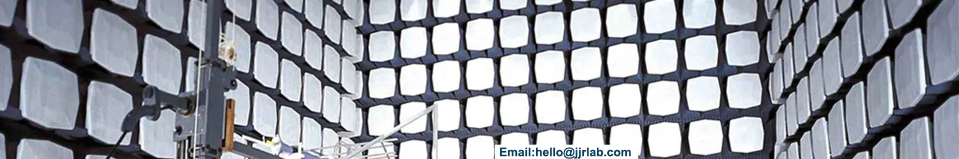
○ 30 MHz – 1 GHz: Test in an open area or semi-anechoic chamber simulating semi-free space, with a 0.8 m-high wooden table, 360° turntable, 3/10 m measurement distance, and an adjustable antenna (1–4 m height) for vertical and horizontal polarization testing. A broadband antenna, coaxial cable, and disturbance measuring instrument form a 50Ω matched transmission system. Impedance mismatch causes reflection and standing waves, reducing accuracy. Quasi-peak or peak detection is used.
○ 1 GHz – 18 GHz: Test in a full anechoic chamber simulating free space, with a 3 m test distance and 360° turntable. Use small-diameter directional antennas in horizontal and vertical orientations (antenna bottom ≥25 cm above ground). The spectrum analyzer uses max-hold and log dB modes, measuring peak or average electric field strength (no quasi-peak). Peak measurement uses 1 MHz resolution and video bandwidth; average measurement uses 1 MHz resolution bandwidth and 10 Hz video bandwidth (equivalent to a low-pass filter).
Radiated Emissions Test Procedure:
1. Place the antenna and receiver 3 m from the EUT’s outer wall, with the antenna center 2 m above ground.
2. Power off the EUT and measure ambient noise.
3. Power on the EUT, adjust antenna height, polarization, and turntable angle to locate the maximum radiation point.
4. Activate different functions of the EUT to find the maximum radiation mode.
5. Rotate the antenna to test horizontal and vertical radiated disturbances separately.
6. Move the antenna around the EUT and select measurement points.
7. Record the highest radiation level as the result.
8. Testing may be performed in an open area or semi-anechoic chamber.
9. Power off the EUT.
EMC Conducted Emissions Test (CE)
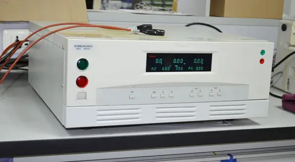
Conducted emissions refer to electromagnetic phenomena where voltages or currents in signal cables become interference sources for other systems. It is often called disturbance voltage testing.
It applies to nearly all DC-powered products with power cables, and many standards also impose requirements on signal/control cables, expressed as limits for disturbance voltage or current (convertible between each other).
Procedure:
1. Place the EUT on a test bench 80–90 cm above ground. The bench surface may be conductive (metal ground plane) or non-conductive, chosen based on real usage: portable devices on non-conductive surfaces, cabin-mounted equipment on conductive surfaces.
2. Connect the power cable to the power grid via a Line Impedance Stabilization Network (LISN).
3. Route cables per standard requirements with specified lengths.
Conducted and Radiated Emissions Testing Standards
European Standards (CE certification)
Emissions Standards
Standard | Scope | Test Items | Remarks |
Multimedia Equipment (MME) | Conducted & Radiated Disturbance (30 MHz–6 GHz) | Replaces EN 55022 & EN 55013; harmonized under EU EMC Directive 2014/30/EU | |
en 61000-6-3 | Residential, commercial & light-industrial environments | Conducted & Radiated Emissions | General standard for products not covered by specific standards |
EN 61000-6-4 | Industrial environments | Conducted & Radiated Emissions | For industrial use |
Immunity Standards
Standard | Scope | Test Items |
EN 55035 | Multimedia equipment immunity | ESD, RF electromagnetic field, EFT, Surge, conducted immunity |
EN 61000-4-3 | Radiated RF electromagnetic field immunity | 80 MHz–6 GHz RF field immunity |
EN 61000-6-1 | Residential, commercial & light-industrial environments | General immunity requirements |
EN 61000-6-2 | Industrial environments | Industrial-grade immunity requirements |
Key Limit Requirements (EN 55032 Class B – Residential)
• Conducted Emissions: 150 kHz–30 MHz, quasi-peak limit 60–50 dBμV, average limit 50–40 dBμV
• Radiated Emissions: 30 MHz–230 MHz (3 m) quasi-peak 40 dBμV/m; 230 MHz–1000 MHz 47 dBμV/m
US Standards (fcc Certification)
Standard | Scope | Test Items | Remarks |
fcc part 15 Subpart B | Unintentional Radiators | Conducted Emissions (150 kHz–30 MHz), Radiated Emissions (30 MHz–1 GHz+) | IT equipment, multimedia devices |
Industrial, Scientific & Medical (ISM) Equipment | Conducted & Radiated Emissions | Microwaves, medical devices |
FCC Class A vs Class B
• Class B: For residential environments, stricter limits
• Class A: For commercial/industrial environments, more relaxed limits
International Standards (CISPR Series)
Standard | Description | Status |
CISPR 32 | Emission requirements for multimedia equipment | Current, replaces CISPR 22 & CISPR 13 |
CISPR 22 | IT equipment emissions | Superseded by CISPR 32:2019 |
CISPR 16-1-1 | Specification for radio disturbance and immunity measuring apparatus | Basic measurement standard |
CISPR 11 | Industrial, scientific and medical (ISM) equipment | Current |
CISPR 14-1 | Household appliances, power tools | Current |
Test Frequency Range Summary
Test Type | Frequency Range | Applicable Standards |
Conducted Emissions | 150 kHz – 30 MHz | EN 55032, FCC Part 15, CISPR 32 |
Radiated Emissions | 30 MHz – 6 GHz | EN 55032, FCC Part 15, CISPR 32 |
Radiated Immunity | 80 MHz – 6 GHz | EN 61000-4-3 / iec 61000-4-3 |
Standard Test Setup
General Conducted Emissions Setup
1. Bundle excessively long cables into 30–40 cm harnesses.
2. Terminate I/O signal cables with matching resistors; no hanging ends.
3. Projection distance between EUT and LISN is 80 cm.
4. All cables ≥10 cm above ground plane.
5. Hanging cable ends ≥40 cm above ground plane to avoid excessive spatial coupling.
Vertical Equipment Conducted Emissions Setup
1. Bundle excessively long cables into 30–40 cm harnesses.
2. Terminate I/O signal cables with matching resistors; no hanging ends.
3. Isolate EUT from the ground plane.
4. All cables ≥10 cm above ground plane (greatly affects common-mode current).
Purpose of Conducted Emissions Testing
To assess and regulate conducted electromagnetic disturbances emitted by electronic products through power, signal, control, or grounding cables.
When noise frequency is below 30 MHz, interference mainly affects the audio band. At such low frequencies, cables are electrically short compared to the wavelength (10 m at 30 MHz), so radiation efficiency is low. Measuring noise voltage induced on cables effectively evaluates electromagnetic interference. This conducted noise includes intermittent noise such as clicking sounds from irons, washing machines, and rice cookers. This test measures continuous disturbance voltage below 30 MHz.
Email:hello@jjrlab.com
Write your message here and send it to us
 Do I Need CPSC eFiling for Toys
What is the CPSC eFiling Requirement for Amazon Se
Do I Need CPSC eFiling for Toys
What is the CPSC eFiling Requirement for Amazon Se
 What Products Require Direct Verification by Amazo
 Amazon Toys TIC DV Validation
 Austrian Amazon EPR Mandatory Compliance
 The Differences Between CTA Network Access Certifi
 Where to Get German LFGB Testing Done?
 966 Fully Anechoic Chamber
Leave us a message
24-hour online customer service at any time to respond, so that you worry!